
Battery and Cable Connectors: Types, Fitment and Replacement
Match battery terminals to cable connectors, verify polarity and clearance, choose a safe cable repair, and follow the correct connection order.
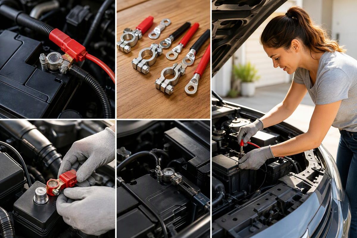
The battery terminal and cable connector must match in type, size, polarity and location. A battery can have the correct voltage, chemistry, capacity and case dimensions yet still be unusable because its terminals do not accept the vehicle’s cable ends—or because the positive and negative terminals are in the wrong positions.
Do not choose a replacement from a photo alone. Check the battery label or data sheet, compare it with the installed battery, and confirm the specified group size and terminal arrangement in the vehicle or equipment manual.
Select the battery terminal and cable end to check whether they are a direct mechanical match.
Direct Mechanical Match
An SAE tapered split clamp is the matching cable end for an SAE top post. You must still verify polarity, post position, cable reach, clearance and electrical specifications.
Source: Battery Council International terminal reference and the manufacturer guidance cited in the article. A mechanical match does not establish battery or vehicle compatibility.
Common Battery Terminals Require Specific Cable Ends
| Battery terminal | Matching cable connector | Typical applications | Main fitment check |
|---|---|---|---|
| SAE top post | Tapered split clamp | Many North American cars and light trucks | Clamp, polarity, post position and hood clearance |
| DIN or EN/JIS top post | Matching post clamp | Many European-size automotive batteries | Exact post style, recessed location and cable reach |
| JIS pencil post | Smaller post clamp | Some compact and Asian-market batteries | A standard SAE clamp is too large |
| Side terminal | Threaded side-terminal bolt | Certain passenger vehicles, including older GM applications | Thread, bolt length and specified torque; the bolt must not bottom out |
| Threaded stud or receptacle | Ring lug secured by a nut or bolt | Commercial, powersports, RV, marine and auxiliary systems | Thread diameter and pitch, lug-hole size and torque |
| Marine or dual terminal | Post clamp and/or ring lug | Boats, RVs and multipurpose batteries | Use the terminal and hardware specified for the installation |
| Flag, auxiliary or specialty terminal | Model-specific connector | Auxiliary batteries and specialized equipment | Exact battery and equipment specification |
The Battery Council International terminal reference distinguishes SAE, DIN, EN/JIS and JIS pencil top posts from side, auxiliary, threaded, marine and other configurations. Terminal type also varies by group: for example, BCI lists Groups 70–76 with Type S side terminals, while many common passenger-car groups use one or more top-post configurations.
A dual-terminal battery does not make its connections interchangeable. Its top posts and threaded terminals are different mechanical interfaces and may have different installation limits. Follow the battery maker’s instructions rather than stacking improvised adapters or hardware.
Battery Size Alone Does Not Establish Connector Fit
Before buying, verify all six parts of the fitment:
- Case size and hold-down: The battery must sit fully in the tray and engage the original restraint.
- Terminal type: SAE, JIS, side-terminal and threaded connections require different cable ends.
- Polarity layout: Confirm which side carries positive and negative when the battery is oriented as it will be installed. An
R,For another suffix can signal different dimensions or terminal placement, but suffix meanings are not universal across naming systems. For one practical comparison, see the Group 27 and 27F terminal layouts. - Cable reach: Both cables must reach without stretching, crossing over the battery or rubbing a sharp edge.
- Clearance: A closed hood, seat base or metal battery-box cover must not contact a terminal, cable end or accessory stud.
- Electrical specification: Connector fit does not prove that the battery chemistry, CCA, reserve capacity or charging requirements suit the vehicle. AGM, EFB and flooded batteries can share a case and terminal layout while requiring different charging treatment; see how to choose a compatible 12V lead-acid charger.
An adapter may make two parts physically meet, but it can add height, loosen under vibration or create another resistance point. Use one only when the battery or equipment manufacturer permits it and the finished connection preserves the required clearance.
Replacement Cable Ends Must Fit the Terminal and Conductor
Match a replacement connector to both sides of the joint:
- The clamp must fit the battery post or thread exactly.
- A ring lug’s hole must fit the fastener closely enough to seat flat and remain correctly aligned.
- The connector barrel must match the cable’s conductor size, not merely its outside insulation diameter.
- The conductor must support the expected current over the complete circuit length.
- The finished cable must remain flexible and supported so it does not load the battery terminal.
Do not downsize a starter cable simply because a smaller terminal is easier to install. Cable length and current determine the required conductor area; excessive resistance produces voltage drop and heat. ODYSSEY advises sizing cable for expected current and considering heavier cable when a run must exceed 6 ft (1.8 m) (ODYSSEY installation manual). For RV, boat or inverter wiring, use the equipment manual’s cable and fuse tables rather than a generic automotive gauge chart.
For a ring-lug repair, use the correct die and crimping tool. The lug must sit flush against the terminal surface; do not place a washer or fuse between the lug and that contact face. Victron also warns that insulation trapped in a connector increases resistance and can lead to overheating, while exposed conductor creates a short-circuit risk (Victron DC wiring guide). Insulate, seal and support the repair as required for its environment.
A complete cable or original-style terminal assembly is usually the better repair when corrosion has traveled under the insulation, strands are missing, insulation is heat-damaged, or the original terminal contains a current sensor, fuse block or distribution hardware. A serviceable cable with a simple damaged end may accept a correctly sized repair terminal if the vehicle or equipment instructions allow it.
Connector Torque Depends on the Exact Terminal
There is no universal torque for battery connectors. Threaded studs, side terminals, adapters and top-post clamps have different limits, sometimes within one manufacturer’s range.
ODYSSEY, for example, specifies 60 in-lb (6.8 N·m) for the 3/8-16 side-terminal receptacles on its Group 75 and 78 batteries, but different values for its studs and metric receptacles. Trojan likewise publishes terminal-specific values and warns that overtightening can cause post breakage, post meltdown or fire (Trojan torque table). Use the specification for the exact battery or vehicle.
A threaded side-terminal bolt must be the correct length. A bolt that bottoms out can appear tight without clamping the cable terminal securely. Top-post clamps also require the specified tightening method; forcing an unsuitable or damaged clamp onto a post is not a substitute for the correct connector.
Disconnect Negative First and Reconnect It Last
For battery replacement, switch off loads and follow the vehicle manual. Some vehicles require model-specific isolation, battery registration or electronic reset procedures. For a conventional single 12 V battery:
- Wear eye protection and gloves, and remove metal jewelry. Do not work on a cracked, leaking or otherwise damaged battery.
- Disconnect negative first, then positive.
- Inspect the tray, hold-down, cables and connectors; clean or replace parts as necessary.
- Secure the new battery before attaching the cables.
- Connect positive first, then negative.
- Tighten each connection to specification and refit the terminal covers.
ODYSSEY’s replacement procedure uses that same disconnect-and-connect order. Jump-starting is different: use the vehicle’s designated jump points and prescribed sequence. In Clore Automotive’s portable-jump-starter procedure, the positive clamp connects first; the negative clamp then goes to a suitable heavy, unpainted vehicle ground or the manufacturer-specified ground point—not automatically to the battery’s negative post (Clore jump-starting guidance).
After installation, a connector should not rotate or shift by hand. If the vehicle still cranks slowly, test voltage drop across the positive and ground paths while the circuit is under load rather than assuming the new battery is defective.